Table of contents
Prerequisites
Instruction set architectures
A instruction set architecture (ISA) describes the functions of a processor. It specifies:
- assembly instructions like
mov,ldr, andadd - registers like
r0, lr, sp - addressing modes
- register direct addressing
- register indirect addressing
- immediate data
- pc-relative addressing
- operating modes like privileged and unpriveleged execution
- exception handling
In this way, the ISA is a contract between chip architects and compiler designers. A microarchitecture is a hardware design that implements an ISA. Instruction sets come in two forms, reduced instruction and complex instruction sets.
Complex instruction sets
Complex instruction sets were popular until the 1980s. They had features to make assembly programming easier:
- Complex operations like (x86)
movsb(copying a byte string in memory) - ALU operands can be specified directly from memory (as opposed to load-store architecture)
- Complex addressing modes
They are distinguished by variable instruction lengths, smaller executables, but are very hard to pipeline.
Reduced instruction sets
Reduced instruction sets are distinguished by their set of simple operations.
- ALU operands can only come from registers or constants (load-store architecture)
- Simple addressing modes (register-direct, register-indirect, immediate, and pc-relative)
Literature from the period emphasized the transition from code largely being written in hand-assembly, where complex instructions reduced development time and were easier to optimize, to high-level languages where a reduced instruction set was easier for compilers to use.1
RISC ISAs:
- have fixed instruction length
- produce slightly larger executables
- facilitates pipelining, which leads to more runtime optimization
A comparison: the RISC must load the memory into a register before performing any operations.
| CISC (M68000) | RISC (ARM) |
|---|---|
add d0, label | ldr r1,=label |
ldr r2,[r1] | |
add r2,r0,r2 | |
str r2,[r1] |
LEGv8
LEGv8 is a simplified version of the ARMv8 ISA.
Its instructions are all 32 bits wide.
Its registers each store 64 bits and are numbered from x0 ... x31.
Representative instructions include add, ldr, str, and cbz.
LEGv8 has three instruction formats or encodings:
- R-format (
add):<opcode 11> | <Rm 5> | <shamt 6> | <Rn 5> | <Rd 5> - D-format (
ldr1):<opcode 11> | <offset 9> | 00 | <Rn 5> | <Rt 5> - CB-format
ARMv7 assembly
Memory-mapped I/O

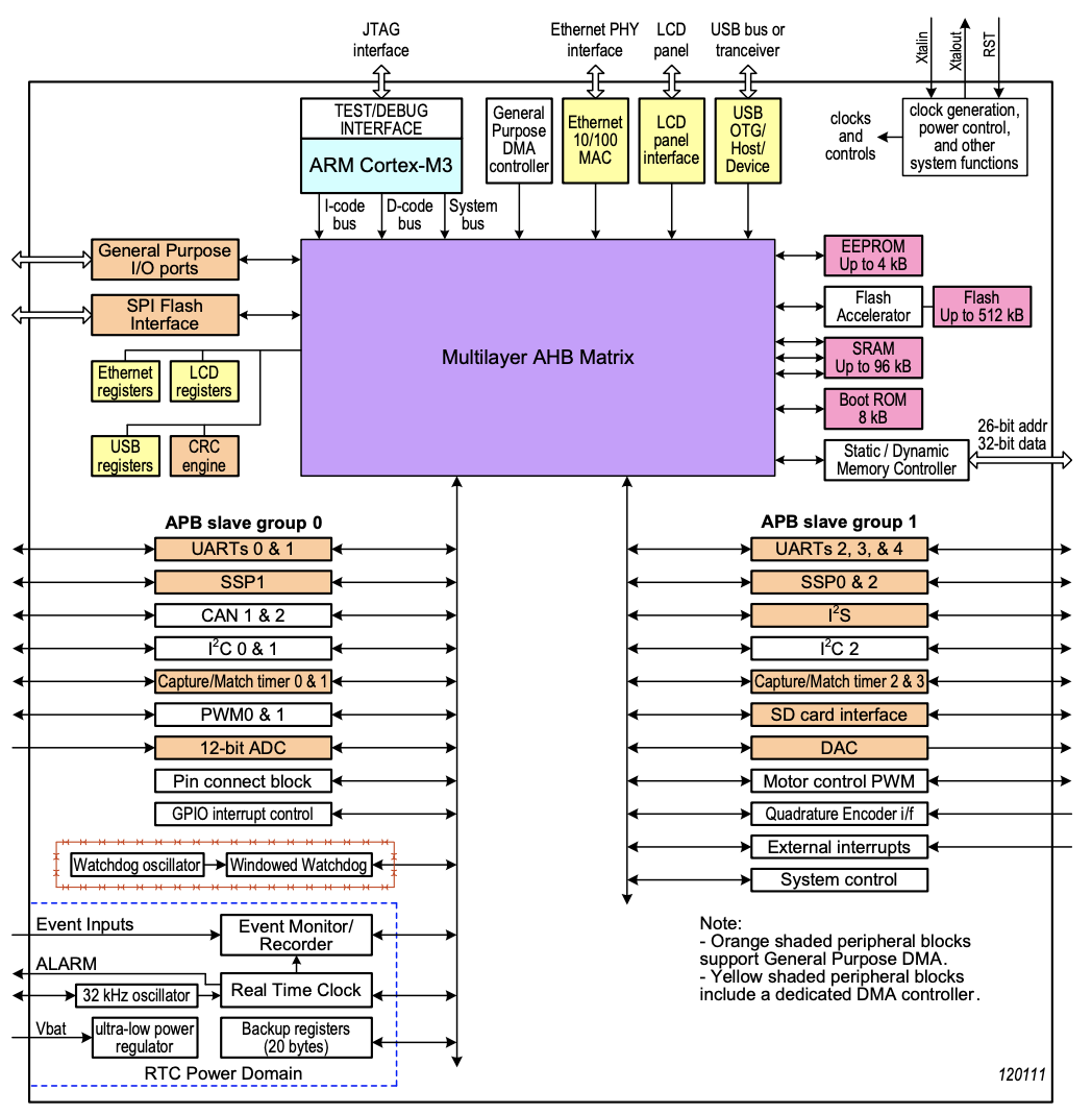
The LPC1768 memory map is of the form
| Starting address (hex) | Description |
|---|---|
0000 0000 | Memory (flash, ram, rom) |
2000 0000 | I/O data |
| GPIO ports | |
4000 0000 | APB (UART, CAN, WDT) |
| AHB (ENET, USB, DMA) | |
6000 0000 | Unused |
E000 0000 | System services (interrupt controller, system tick) |
The device bus interface is provided by any I/O device connected to the microcontroller unit (MCU). It consists of five elements:
- Address decoder: recognizes addresses for its registers
- Bus logic: combinational logic that responds to bus operations
- Control register(s): affect device behaviour
- Status register(s): describe device state
- Data register(s): pass data to and from the processor
Polling I/O
When given a time-varying signal, we often need to sample the data at regular periods $T_0$. Polling I/O accomplishes this by polling, or checking, the device status registers until it sees that the device is ready for an operation. The steps are:
- Read status register
- Check "done" bit
- If not set, goto (1)
- Read and write to the data register
- Process the data
- Goto (1)
Interrupts
Vector table
The vector table is a table in memory of handler addresses.
- I/O device asserts its IRQ signal
- Interrupt controller (IC) looks up the handler address in the vector table
- IC invokes the handler
- Handler runs (IRQ is dropped)
- IC resumes the interrupted program
References
David A Patterson, David R. Ditzel, The Case for the Reduced Instruction Set Computer, Published 1980, https://inst.eecs.berkeley.edu/~n252/paper/RISC-patterson.pdf
Arm Ltd, Procedure Call Standarde for the Arm Architecture, Release 2019Q1